Showing posts with label Microwave. Show all posts

2026-04-29

First QSO(s) on a New Band: 5.7GHz.

Yesterday evening I went a bit up-hill to make experiments on 2.4,  5.7 and 10GHz.

The place is only 2km from my home, and with aspace to park and set up a portable station.

I was bringing my IC-905 with the 10GHz unit added, and three antennas:

For 2m-70cm-23cm a vertical with a magnetic mount for the car

For 2.4GHz a tiny panel antenna (Hybrid double quad) (10dBi?)

For 5.7GHz a tall and narrow panel antenna, about 18dBi gain

For 10GHz a 22dBi horn antenna.

Modest station, loosely mounted on a  mobile camera support.

I have made tests earlier on 2.4GHz, from a hill with no car access a bit furthe away, and from the place of yesterday.

The first test on 2.4 GHz didn't go well, as I had the antenna mounted with vertical polarisation, and the others were using horizontal. that can happen when you don't look carefully at the cable coming out from the feed point. The antenna was a yagi mounted inside a pipe "radome", so it couldn't be seen as such. Yess, silly me....

Second test was quite sucessful, with solid signals locally, at distances of about 25km, even using FM.

Yesterday's test started poorly, because the vertical on the car was absolutely not working. SWR infinite...

Looks like a bad connector, I will have to check, because it's a useful backup coom.. So no way of discussing the experiments on air.

So a phone call to OZ1GIN, working with indoor antennas on microwaves. Things did work well enough from the nearby hill, (essentially line of sight) so it was interesting to see how the system worked from a less ideal site.

Fist experiment: Test on 10GHz. I could hear the local beacon hidden behind a hill, so my system was certainly working. He could also hear the beacon with the indoor antenna. Trying to point the antennas we took turns with transmitting "beacon" signals and adjust antennas. 

No signals detected from either side. 10GHZ wasn't working.

On 2.4 GHz I was using a considerable smaller antenna than the first test. Signals were weak, but a QSO in CW could be made.

The 2.4GHz system was also less, as in the previous tests the cable was connected directly to the "base" RF unit, and yesterday the 2.4GHz signals went through the 10GHz unit.

There is definitely room for improvement. 

Then OZ4HZ (as agreed) made a test. A QSO with SSB was possible, although with weak signals.

2.4GHz with the smaller antenna was a qualified succes. 

On 5.7GHz OZ1GIN started in the same way as on 10GHz, with sending beacon signals and turning the antennas. After a few tries, where we also needed adjusting frequency a bit, we managed to make a CW QSO, with slightly better signals than on 2.4GHz.

The signals from OZ1GIN had some scatter sound, warbling a bit, I had not expected it on the distance of 25km, but hinking about it, I probably should. There was also some moderate fading.

Then OZ4HZ, working from an apartment block came with SSB, and we could also work a bit better than on 2,4GHz. His signals did not have scatter sound, so the path was probably closer to line-of-sight than OZ1GIN.

This was my first and second QSO on 5.7GHz.

Now it's time to improve the setup, mechanically and electrically. I am fully aware that there is a lot of room for improvements. 

I should also think of getting some setup at home for those frequencies. Limited height and terrain, including neigbour's houses and some trees will put quite some limits on that, but it should be possible to male some occasional contacts, for example via rain scatter on 10GHz. I have some experiments in mind, probably more on that later.

2026-03-03

Tidying and Birthday Present.

 As the house is a total mess, a massive task of tidying has been started. It will likely last the whole year, or longer. 

The first task was getting down to the surface of the work desk, test bench.

I found most of the test bench surface ;).

Then I had my birthday recently, and I decided to get myself a present.

I have started doing a bit of microwave activity, and I got myself a TinySA a while ago. This measures up to about 6GHz and has a generator for the same frequency range.

It looks like the generator can show harmonic output well over the 10GHz range. Interesting.

So I decided that I should be able to check filters and amplifiers up to the 6GHz range, and purchased the corresponding NanoVNA, got it calibrated with the calibration set that came with the VNA. 

I have created a few presets, and saved them into the VNA:

350 - 550MHz

2 - 3 GHz and 

5 - 6GHz. 

There is space fro a few more, so I will likely add a range for the 3.4GHz band, the 1296MHz band and maybe one other.

The initial test today showed pretty realistic results, so I consider it a success.

Now I can do a bit of experimentation again. There is a plethora of small and big projects for all frequencies, from 472kHz up to 10GHz, at least. The experimentation may be slow, but it's possible.


2024-04-07

1296MHz etc. Portable. New Toy.

 I have got myself a new transceiver. For the microwave band I am now testing a new IC-905 and the 10GHz module (transverter).

This rig runs 10W on 144,432 and 1296MHz, and 2W on 2.4GHz and 5.7GHz, and 500mW on 10GHz.

It has 2 mast mounted modules, one transceiver for 144,432,1296MHz, 2.4GHz and 5.7GHz, the other converts the 2400MHz band to 10GHz. Everything is controlled fro a control module that resembles the IC-705, and it feeds 40V up to the modules via PoE (Power over Ethernet), and the rig has a common N-connector for 144,432 and 1296MHz, and separate SMA connectors for each of the higher bands.

The system has a built-in GPS for controlling the reference frequencies.

Time to do some tests, I started a few days ago. First, get it up on a tripod in the living room, and the tests could begin.

The very first tests was checking that the GPS system worked, and even indoors it would lock. I should be right on the frequency in the display.

I have not yet tested the 144 and 432MHz parts, but I set up a small 12 elements yagi in my living room, just 0.5m (about 2 feet) above the floor. To my surprise the OZ7IGY beacon located behind some hills about 20m higher was clearly audible. First successful test done!

I tried setting up a 2400MHz yagi (16 elements), and I was not surprised that I heard nothing from OZ7IGY. I could hear noises that I suspect came from the local wireless network. 

Using a PCB log-periodic antenna, exactly the same happened on 5760MHz. 

On 10GHz I set up a synthesizer generator in the house, and got a strong signal, using a PCB patch antenna array (16 patches in a 4x4 array). The transmit side was tested using my QO-100 receive setup, and worked nicely.

Today it was time to get out in the field. Temperature in the 15-20C range and some sunshine, it was a beautiful day to get started. I drove the system a few km from my home, just a bit up a hill, but not to the top (no driving permitted there). It took about 1/2 hour to get it up, and the test could begin, using the exact same antennas as in the indoor test.

The 1296MHz antenna was about 2.5m above ground and turned towards OZ7IGY. Signal was booming in, above S9. RX Success!

The 2400MHz antenna was very low above ground, about 70cm. The signal from OZ7IGY was a solid copy, though not very strong. RX Success

On 5760MHz the beacon was all but inaudible. I thought I could hear a signal tuning around the frequency, but I was not 100% sure, so I say no reception.

On 10GHz no reception (not surprising).

On 5.7 and 10GHz the cables used were some surplus semi-rigid cables with angled SMA connectors, so I suspect high losses, but the test had to be made. I am sure I could have gone to a different location with no hills in the way, and get reception, but I stayed because there was one more test to do.

I called on the local FM frequency (1297.500), and as I had announced my activity locally, there was immediate calls from 2 stations in the Copenhagen area and one in Sweden, just across the water. The SM7 station was 43km away and a solid S9, with a fairly unobstructed path.

One of the locals alerted a station in the other direction where there are some obstructing hills. Call made and good signals at 43km in the more obstructed path.

This was "first light" for my IC-905, and I am satisfied with the results. I can see many possible improvements to the system, so I have quite some work to do with the mechanical part of the portable system. Mainly better antennas for 2.4, 5.7 and 10GHz, and a better way to fix those antennas to the tripod. 

At today's test the 1.3 and 2.4GHz yagi antennas were mounted using gaffer tape, so there is already some hardware that I will need to go get, some holes to be drilled, so I can mount those antennas to the mast in a more secure way. As a first test, it was good enough, though.

2024-01-18

Fault Finding in an Old 10GHz Transverter.

In the autumn I made a first test of a home-made 10GHz transverter I got my hands on, and started testing.

The initial test was a simple connection to an older FT-290 transceiver, and going out to spme place a bit higher than where my house is located.

I was listening for the beacon OZ7IGY at a distance of about 25km. Nothing in the garden. If I placed an satellite TV LNB about 4m above ground I could hear the beacon, very weak, because it is behind some hills about 30m higher than where I am.

I tried to go to a place somewhat higher with the FT-290/transverter setup on a tripod, and tested. Absolutely nothing heard. tuning about 30kHz to either side of the beacon frequency.

So now I got started fault finding.

The first suspicion after talking to a local ham was the 2556MHz local oscillator module. Testing on a spectrum analyzer showed a nice signal with an offset of less than 600Hz. Not bad, this would give an offset of less than 3kHz. The output (to the Qualcomm up/down conversion module) is close to 5dBm, so that looks quite good. I can safely say that the LO module works nicely.

Now more tests are necessary.

 I do need a small 10GHz signal source, and I have thought of using one of the following:

- a low power (0.5W) 70cm FM transceiver with an attenuator and a single diode as multiplier

- a synthesizer PCB with a AD 4350 or 4351 chip, just using the 3rd harmonic. 

At least I can test those with the spectrum analyzer, so I know if there is a strong enough 10GHz signal.

I think the simplest of the two is the attenuator/diode multiplier, so I think I should start there.

2023-09-26

A Bit of MIcrowave.

A while ago I went to a rally and got myself  power amp for 1296MHz.

The amp is built with 4 10-15W power modules and has a built-in linear power supply. It is quite heavy, so it is not suitable for portable use or outdoor mounting. The nominal output is about 50W.

The amplifier has no T/R switch relays built-in, so I will have to make myself an external relay system. As I am using a preamplifier I will have to use a sequencer as well, as I would not like to destroy the preamp.

Yes, I have already destroyed one preamp for 1296, not by transmitting reverse into it, but likely for one of 2 reasons. Either a lightning strike nearby, or (more likely) transmitting up to 100W on 2m from an antenna a few meters away. The antenna for 1296 was a 3 band antenna for 144/432/1296MHs, with no 1296MHz filter. 

I noticed it one day, when the preamplifier was switched in, the noise increased, but the signal from the local beacon went down into the noise. Bypassing the preamp reception had a much better signal to noise ratio. I can replace the preamp for a next try, and I intend to mount a triplexer (144/432/1296), so the 2m and 70cm signals into the 1296MHz preamp will be attenuated considerrably. More to do, once again, and I will need to call for assistance to get the system up and down.

I am still thinking of a portable system for 1296MHz, so I can operate from hilltops or other suitable places. That is a bit further into the future.

Now for some 10GHz news.

I found an old transverter, built with much assistance from a friend. It has been dormant for several years, and I have retrieved it from my storage. A mounting plate for a tripod is included, so the system is made for portable use.

This is a quite old construction built with modified modules from Qualcomm, and should privide about 500mW of power. 

The system was "born" with a home made waveguide transition and a 48cm dish. During transport the dish has been bent out of shape, so it will need some repair.

I intend to use a smaller horn antenna (15dBi gain) with WR90/WG16 waveguide  for the first experiments.

The wavequide was using a non standard flange, so I deeded to use a modified waveguide extension, modifying the flange used at the transverter end, and standard at the horn antenna. That modification is done.

I also got myself an old FT290R (1) transceiver that should be suitable for controlling the transverter. The T/R switching uses a DC (bias) voltage (>5V) for switching into TX mode, and the FT290 should provide that voltage to the transverter through the antenna cable. Unfortunately the voltage drops below that threshold when the transverter is connected (only 2V). Not good, so a modification or repair of the FT290 is needed, or maybe a modification of the sensing circuit in the transverter.

The receive side appears to function properly, there is a sufficient increase of noise in the FT290 RX when the transverter is switched on.

When the TX part is activated, however, there appears to be a quite low output from the transverter, the needle of the built-in power meter hardly moves, but it does move. More to investigate.

There is a possibility that the negative gate voltage for the PA stage has dropped out ... Oops, new PA module needed. It's not a disaster if this is the case, I do have another PA module.

We shall see when I get more tests done, and when I can get it up and running. Hopefully before winter.

2023-05-21

PA Transistors Found at the Rally.

 There was one more thing I found at the rally.

1.9GHz PA transistors capable of about 60W linear output, apparently LDMOS. 

I found a set of 14 pieces packed in an antistatic container.

The transistors come from CREE Microwaves and are marked LGA19060-171. Does this relate to 1.9GHz and 60W output? 

I do not know if they are internally matched. If they are not they could be interesting for a number of PA constructions for different frequency ranges.

My main interest will be to see if I can get those running on 1296MHz. Two of those should be capable of generating 100W. If they have internal matching an external impedance matching circuit should be made.

Since they came at a low price I can do some experimentation without being afraid of destroying a transistor, and with 14 of them I should be able to make a workable amplifier with them.

I was recommended contacting a local amateur, as he may have some tips for overcoming the possible internal matching, so I can use the transistors well outside the design frequency.

As there most likely will be a lot of experimentation, this will be a future project, as there are already so many ones already to be made.

If anyone knows more about these transistors, please let me know.

2023-01-28

This Year's Challenge. Small and Mini Projects. And Antennas.

This year, as opposed to last year, I have the intention to do some more building and construction activities. Last year was the year of 365 QSOs with 5W, later 365 with just 5W and solar power.

This year is more about getting some physical things done. This does not mean that I will not do much operation. Especially as propagation is among my great interests.

My antennas need an overhaul, and an update. At the moment I have:

For HF: R6000 for 10,12,15,17 and 20m (6m usable for some monitoring). Then a 5 band dipole, 10,15,20,40,80m, passable on 4 and 6m. Also a 30m long wire antenna with some limited counterpoise. This is passable for all HF bands and barely usable for 6 and 4m, and should be usable if I want to listen on 8m (40MHz). a 1/2 wave antenna for 10-11m is OK.

For VHF/UHF I have the V-2000 vertical from diamond running 50, 144 and 432MHz. A cable is running into the shack to a triplexer, running up to 3 different radios. A short (1m long) dual or triband antenna is used for monitoring 2m and 70cm, and a clover leaf ("Big Wheel")  for 2m. My 4m vertical is not standing upright at the moment, so it is not very useful.

This year I want to get up and running on a few more bands/modes. That requires new antennas and some kind of rotating functionality.

For 2m I want to do some more SSB/CW etc. (DX) activity. The 4 element yagi mentioned in an earlier post should do that.

For 70cm I also want to add DX activity. The 11 (really 8) element yagi is intended for that.

23cm: I have had some activity on that band a few decades ago, and because there is an activity group active now on this band I want to get some activity going again, this time with better equipment than I had back then. The 16 element yagi is intended for that.

I am (a bit) active on the QO100 geostationary satellite, transmitting on 13cm and receiving on 3cm.

I want to become active  with terrestrial on those bands, even if it will be with small antennas form home. Those are more directional than the VHF/UHF antennas, and need to be rotated as well.

I suspect that some portable operation from hilltops will be good for the microwave bands (above 1GHz), as I have obstructions in several directions, so range is a bit limited. This means that both a home station and some portable equipment is needed. I am building up my stock of equipment and antennas, and no, I do not expect to finish all of it this year.

In any case I want to be able to extend the number of bands where I have made at least one QSO. In this case we are talking about 2400MHz and 10GHz, and maybe later on the two bands in the other end of the spectrum, 630m and 2200m.

Then there are the small projects and mini projects, I have the goal of making at least one or two of those every month, as they are limited in scope.

One (two) of the somewhat larger projects are about assembling two QCX+ kits I have, one for 20m and one for 60m. Those are 5W CW transceivers, and should provide much fun in the future.

2023-01-27

Mini project #4B: Small 70cm Flexa Yagi, and Some Thoughts on the Higher Frequencies.

When I purchased the small Flexa Yagi antennas some time ago it was the intention to make a compact, not too visible antenna system for 2m/70cm/23cm SSB/CW etc operation. At the time I had chemo therapy, so everything went too slowly, and the project almost died.

This project has now been resurrected, and I got the 3 antennas assembled. 

- 4 element yagi for 144MHz

- 11 element yagi for 432MHz (strictly speaking 8 elements, as there are 3 reflectors making a reflector plane).

- 16 element yagi for 1296MHz

The Flexa antennas have very thin steel elements (and a not too heavy boom), reducing the visual impact of the antennas, as I wanted

All these antennas are made for mounting in front of the mast, i.e. "behind" the reflector, so the mast will not interfere with the function of the antenna by blocking part of the elements, especially on the higher frequencies.

Having all antennas front mounted will create an imbalance of the load on the rotator, so I am thinking of making a compromise here: Mounting the largest antenna (the 4 el. for 2m) on one side of the mast, then mount the 70 and 23cm antenna in the opposite direction. This will make the operation a bit more cumbersome, but I think it can be done.

I may add a Moxon Rectangle for 4 and 6m to the system. This is a rather small antenna and will not add significantly to the visual impact.

Further, some small antennas for the 2400MHz and 10GHz band are expected to be added. No parabolic dish there, just some tiny yagi or patch antenna for 2400 and a small horn antenna with a transverter for 10GHz. This is for later, but initially a LNB (frequency stabilized), maybe with a small horn extension will be mounted for 10GHz monitoring purposes.

I will need to mount this on a rotator. No need for a heavy duty one, so I am looking into options.

I intend to mount the system on top of an old apple tree where I have some antennas already.

For SSB/CW (DX) work I have had a clover leaf ("Big Wheel") antenna mounted right on the top of the tree, essentially invisible, and it has provided some DX on 2m.

What kind of performance can I expect from this system.

On 2m, the stated gain of the 4 el. antenna is 7.6dBd. This may be exaggerated, but compared to the old clover leaf antenna I expect to mount the 4 el. 2-3m higher and less obstructed, so I would expect a performance improvement of approximately 10dB over the clover leaf antenna. With a good preamp at the antenna, and also an added PA in the shack I should have a solid performance boost, compared to the current system.

On 70cm, with a stated gain of 10.2dBd the system is a very modest, but some DX activity should be possible.

On 23cm, with a stated gain of 14.2dB (exaggerated?) I would expect some interesting occasional DX activity, especially if a preamp and a PA (25W?) is mounted near the antenna.

On 13cm this system will just be playing around , maybe with some interesting DX in the best directions I have, but I do not expect much there. 

On 3cm  the system is very modest. I may be fortunate enough to make some DX under excellent tropo conditions, and possibly some rain scatter QSOs. 

For the higher (microwave) bands some hilltop operation is probably a much better option, but the capability of some modest home operation is good to have.

2023-01-20

Mini Project #2 (IC910) finished.

 The addition of the 23cm band to the IC910 is now complete.

After disassembling, checking the (flat) cables etc the fault was still there.

A complete reset of the CPU, losing all memory channels, cured the problem. The radio has been running all evening without trouble.

This concludes mini project #2.

I still need to set up an antenna or two for 23cm, but that is for later.

2023-01-10

Mini Project #1.

Before the NanoVNAs became widely available it was tricky to find low cost test equipment for testing SWR or return loss in the low GHz range. 

At the time I did find one possibility: The transverter-store in Ukraine sold some low cost impedance bridge PCBs, so I got myself one.

The PCB bridge circuitry looks like this:


Looking at a Youtube video I found that the PCB has a fault. The bridge has 2 50Ohm resistances, made up by two 50Ohm resistors that should be connected in parallel. On the PCB he tested, and on mine, this is not the case. No connection between 2x two islands on one side of each pair.

Now, this is not difficult to correct. A short piece of wire  mounted at the junctions between the resistor pairs solve this.


A quick test using my NanoVNA 2 showed a shortcoming of the NanoVNA output level (too low), but also gave an indication of the functioning of the bridge.

With a 6dB attenuator as the DUT (Device Under Test) the return loss showed close to 12dB, as it should.

Testing a 10dB attenuator the same way showed that the return loss went down into the noise of the NanoVNA. Close enough to 20dB, so I accept the reading as correct, and that the bridge is working properly.

That is the end of mini project #1 of this year.

Will I use this bridge a lot? Not really, but I did want it to be in working order. It is now going into the test PCB pile as a working unit.

The NanoVNAs that came out after this are much easier yo use, and much more versatile. The cost is not prohibitive, so in the lab I will be using a NanoVNA F (I think is the designation) for frequencies up to 1GHz, and a NanoVNA v2 for up to 4GHz.

2022-12-25

Challenge(s) for Next Year.

 A "few" words on what should be next year's challenge.

0) The  open home brew challenge goes on. This is all about making at least one QSO on as many bands as possible, with home made equipment. This could be a kit I built, a fully home constructed transmitter and/or receiver, or modified versions of equipment not designed for amateur radio.

I do intend to get some more kits built next year, and use some of those already built for HF band monitoring. A part of the propagation study may include a WSPR and/or WRSS transmitter, and/or some WSPR/QRSS monitoring, and more bands with FT8 monitoring when I am not actively operating on the bands.

Apart from the kits, I may get to some more home construction. We shall see.


1) The primary challenge for 2023 will be all about improving the solar power system and its efficiency for the amateur radio station. 

In particular, all systems for monitoring the radio propagation has the highest priority. This includes both the improvement of the capacity of the solar panel and battery system and reducing the power consumption of the receiving systems.

More solar panels are needed for charging the battery. I expect to increase the peak "capacity" of the panels to somewhere between 600 and 900W. The precise configuration is yet to be decided. Currently I have a peak capacity of 250W and a non-optimal position for the panels.

An improved system of solar charge controllers. MPPT controllers are inherently more efficient, though they tend to be more noisy in the radio spectrum. I found some that seem to be relatively quiet, but the3y are not yet tested at full charge current. I suspect that they can be useful with good RF filtering at the inputs and outputs.

Improved battery capacity. The 12V system for the station should be updated to 400Ah capacity at 100% charge.

The aim is to provide pure solar power to the minimum requirements of the station all through winter.

This leads to the next part: Minimizing the power requirements of the station, especially the parts that will be required to run 24/7, or many hours per day, such as some propagation monitoring and monitoring e.g. local traffic on 2m.


2) The other challenge is concerned with microwave activity (above 1GHz) The aim is to make at least a first QSO on a few microwave bands. starting with 2.4GHz and 10GHz. Long ago I was active on 23cm, but I would very much like to get going on that band, too. If I can get away with making experiments on 3.4, 5.7 and 24GHz, that would be nice, too. Improving the QO100 system is part of this, too.

I am already active on the QO100 satellite. This means that I have transmit capability on 2.4GHz and some receive capability on 10GHz.

This system is rather primitive, and many improvements can be made to it, especially on the receive side.

a) Further, I located a 23cm (1.3GHz) module for the IC-910, as well as a more precise and stable reference oscillator (TCXO) for that transceiver. During the winter nights I need to make sufficient space on the lab desk, so I can get going with mounting those, and also make a fresh alignment of the transceiver. Straight forward when the space is available.

As the IC-910 is quite heavy I intend it for home operation only. If I want to go portable on 1.3GHz I will need a transverter and a portable transceiver. I could use one of the FT817s or the IC-705. Both need modifications, so the transverter(s) are not blown up if they get high power TX signals in.

I will still need to get some antenna up for 1.3GHz. This should happen some time in the spring. I expect to use a Diamond X-5000 (I think) for vertical omnidirectional (mostly FM) with a 23cm preamp, and a small yagi, like the front mounted Flexa antenna for horizontal polarization (mostly SSB/CW/digital modes). The horizontal antenna will need a rotating system that needs to be set up. Lots of work.

For portable work I still have a small 23cm yagi that can be used on hills etc.

b) While it is possible to use my up-converter for the QO100 system for transmitting on 2.4GHZ in general, the existing system will be very cumbersome, especially when going portable.

I could possibly use the up converter with the FT817 as the transmit system, and the AR8600 SSB capable "scanner" as receiver. Operating portable from a parked car could be done with this system, but setup will take time, and I am not sure I have the patience ;) 

I think that a much better system can be made with the FT817 driving a transverter from e.g. SG-Labs, and a PA. A bit of relay and sequencing will have to be made. The transverter system should be sufficiently compact for portable use, and should be easily connected to the home system.

Antennas for 2.4GHz? I have some low cost WiFi antennas, such as 16el. yagis, and some patch antennas. Both most likely have a gain of 10-12dBd gain, and can be used for the first light weight portable experiments.

For home use I would likely use a panel antenna with about 20dB gain. Again, as with the 1.3GHz system, a rotator is needed.

c) 10GHz: 

It is possible to make some simple, mostly line-of-sight experiments with a modulated HB-100 module, a satellite LNB and a scanner receiver in the 500-700MHz range. Using WBFM this could likely provide 10-20km range without using anything but the modules, no dish antennas or horn antennas. More, if "external" horn extensions or just a dish for the RX part would be used. This is mostly for portable experiments.

A small system for 10GHz narrow band, with a transverter, is also on my list. Most likely a Kuhne/DB6NT transverter, driven by the FT817 or the IC705.

Other narrow band experiments could be a NBFM/CW transmitter used with a satellite LNB down converter.

First experiments will likely be portable, but long term I should have a small station running from home.

Am I likely to get all of this done? Not really, but the minimum will be to get going from home and portable on at least one microwave band.


On the solar power and monitoring front, at least I will get some improved solar energy and *some* "reduced power" monitoring done.

2022-12-18

Idea Box. QO-100 Downlink Reception.

For quite a while the setup for my QO-100 activity has been rudimentary:

For uplink I have used an old IC-821 as transmitter, with a lot of attenuation, followed by a low cost Chinese up-converter (BU-500) indoors, about 15m RG6 coax, with a so-called 8W WiFi booster that can deliver 2 - 2.5W without modifications, feeding a 4x patch "WiFi antenna and a 1.1m dish reflector.

This provides a decent signal on the downlink side, and certainly never overloads the transponder (triggering LEILA).

For the downlink I am using a 60cm dish, a low cost synthesizer controlled LNB, modified to be controlled by an external 25MHz reference signal.

The 25MHz reference oscillator is indoors in the shack in order to minimize the temperature drift. As this is an uncompensated DIL oscillator there is, of course some drift, up to a few kHz to each side. Actually not too bad for such a simple setup.

The LNB converts the the 10489MHz signal down to 739MHz, so for now I have used an older AOR multimode scanner receiver, the AR8600. This works, and I have made some QSOs, and often participated in the Danish-speaking net on Sundays. It is a bit inconvenient with the drift, as I have to compensate by manually checking the AR8600 frequency for the beacon, and then remember to calculate the offset.

Further, the IF filters in the AR8600 are low cost ceramic filters, so for SSB and CW the selectivity is not what I am used to from my HF/VHF transceivers.

Here comes the idea: The AR8600 has an IF output on 10.7MHz, with a bandwidth of 4MHz. Why not use that to feed one of my HF radios? That way I can use the better filters of the HF radio. On top of that, a quick manual compensation of the LNB frequency drift can be made by switching to one of the beacon frequencies and retune the AR8600 so the beacon is in the pass band of the IF receiver. Then the recalculation of the offset becomes unnecessary.

This is the simplest way to improve the downlink receive system with the equipment I have at hand.

It does require using two radios, as the AR8600 is simply used as a second down converter.

If I want to eliminate the AR8600 from this there is another idea. This requires more construction, so I think I will use the AR8600 in the first instance.

I have some older TV tuner modules with synthesized local oscillators. With a bit of programming of the synthesizer chip using a microcontroller, the Arduino or the like, this can function as a down converter to an IF of 28-40MHz. One little disadvantage is that the TV tuner as-is inverts the IF band. 

This can be eliminated in two ways:

1) a second down converter inverting the band once more. This adds complexity to the system, but can be done without too much building.

2) retuning the RF filters of the tuner, so the LO moves below the signal input frequency. This is the simple way, but requires more test equipment. I do have enough test equipment to do this, so if I go the TV tuner way, this is the likely way to do it.

For now, the AR8600 with HF receiver will be the way, after all the Christmas activities. I am looking forward to improving my QO100 setup.


I am still looking into what next year's "challenge" will be. It should require some activities from my side, on the other hand it should also be fun.

I do think that a part of this will be running the most used parts of my station on solar (with battery backup, of course) hopefully on solar power, even through the winter. I may have to switch parts of it on mains power in the poorest sunlight conditions. The really power hungry parts, like big linear amplifiers will be running on mains power in any case, but they will not be running a lot in any case.

Using only the IC705 in December I have been able to get the battery up to 80%, but that has been with saving the time I was using it.

2022-05-10

Microwave Day.

 In the past week end I went to the Microwave Day in the town of Horsens, Denmark.

Although I have not really built any microwave equipment yet, everyone interested is welcome, and I did also go to the previous one 3 years ago - the ones in the last two years were canceled due to the COVID situation.

I wanted to take things easy, so I did the drive there on Friday, and home again on Sunday.

There were two presentations, one about the Norwegian beacon LB2SHF and the other about the 122GHz experiments. 

After the presentations there was social gathering and microwave talk, as well as Ole, OZ2OE demonstrating his 122GHz equipment. 

There was a small flea market, and I got just a few things. Two N-connector to WR90 waveguide transitions and some ancient 12GHz LNBs with WR75 waveguide inputs.

Because I have some horn antennas for both sizes of waveguide I wanted to have this. The WR90 transitions can be used as they are, and the LNBs can be used in different ways:

1) As a simple down converter, used as-is.

2) As an "active antenna". This requires a modification, taking the output of the 10-12GHz (pre)amplifier to an SMA connector.

3) Removing all the electronics and grinding a bit of material away, the LNB can also be used as a waveguide to SMA transition.

At the flea market I also saw transverters. There was an old version of the DB6NT transverter, complete with a horn antenna for a reasonable price, even if the output power was limited to 30mW. I did not bring it home, but I should probably have bought it, as I do have another 10GHz amplifier module that could have increased the output to about 200mW. A bit of a regret, but there may be other opportunities.

A 24GHz transverter, also at a reasonable price, was seen, but again, I did not bring it home. I know the seller, however, so I could probably still find it for sale.

Then there is test equipment. I had an appointment with another participant, that he would bring a 26GHz spectrum analyzer to check and possibly buy, and I did bring it home. I can now see what the things I build and buy are doing, signal-wise.

In the afternoon there was a demonstration of the 122GHz equipment at a longer distance (5km). Not that far, but not so easy. Signals were heard both ways, though.

Some time ago I purchased a CBNL 10GHz link transceiver module, but there is not much information, so I asked if any of the others had more information.

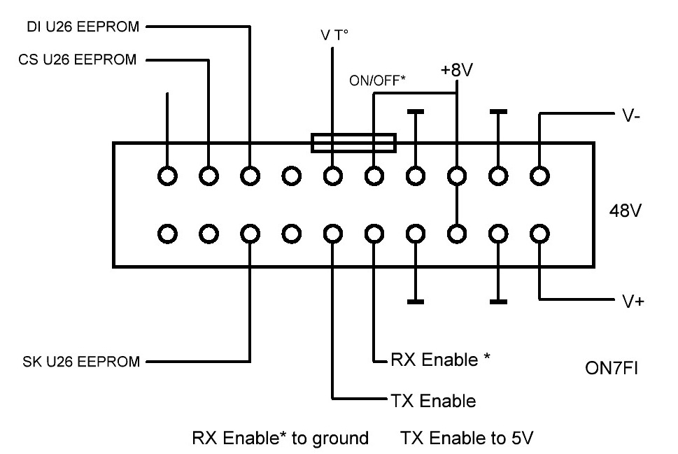
I have found a bit, but I am worried about the simple stuff: How critical is the order in which I connect the power supply. On the on6ll.be website I found the following:

Since it is used in a remote link the "base supply voltage is 48V (see the two connections at the right side of the connector). Then I see that there is a +8V connection The question is now - do I connect the 48V first, or the 8V? What I cannot easily see is where the negative bias for the GaAsFETs is generated. From the 48V converted to 7V, or from the 8V? It is not even clear if the 8V is generated on board when the 48V is connected. 

The other parts I have found sufficient information about to proceed. The LO should be somewhere around 7.5-8GHz, and the IF for the "RF/microwave" section then uses an IF of about 2.4GHz.

The T/R switching is clear enough from the description on the website, even the illustration above.

If any reader knows I would appreciate the information. I simply do not want to make a potentially destructive test, as the GaAsFETs simply will self destruct if the drain voltage is applied before the negative gate bias, as those familiar with GaAsFETs will know. If no reader knows I will have to extend the search.

Good to be back doing social activities again, there will be a few more coming up in the next months. Some of them will be outdoors, and others indoors. The next one is only a few weeks away.

2022-01-10

Late Christmas Present: IC-705. (updated).

 I finally did it!

I ordered the Icom IC-705 portable 5/10W transceiver for MF/HF/6m and 2m/70cm.

Operation is much like the IC-7300 I already had, so it was easy to get started. 

After testing that it worked, the first thing I did was updating the firmware from v1.12 to v1.26, so I could get the latest functionality.

Two things were a bit annoying:

- the spare battery I purchased will not attach correctly. It is a third party part with the Wimo logo on it.

the battery cannot be pressed sufficiently down to get the snap lock engaged - at least not without resorting to "violence".

- frequency tuning steps in FM mode. When setting the steps on one band, say 10m, it changes all bands from 10m up to 70cm. Not good, as on 10m and 6m we need 10kHz (maybe even 5kHz) steps. In Europe the tuning steps are 12.5kHz on 2m and 70cm. I would have been happy to see a 2.5kHz tuning step in FM mode, but no, not available. There are 2 work-arounds: For now I use 0.5kHz tuning steps, so I can hit all the frequencies needed. The other option is storing all the frequencies on the non standard TS in memories. This will take time, but can be done. Ideally the tuning steps should be programmable per band (HF - 6m - 2m - 70cm).

Otherwise this is a beautiful little transceiver, and the first QSO - just a Russian on 20m with 5W - has been done in CW.

The IC-705 will be used for some QRP HF work, but mainly as a base transceiver for microwave transverters. The spectrum display is invaluable for propagation monitoring.

Update 2022-01-14:

I did 17 QSOs until now, all in CW with 5W.  The bands with success were 80-40-20-17-15m. The antenna I mostly use is a very low hanging 5-band dipole with the feed point less than 4m (13ft) above the ground. A few were made with my R-6000, a half wave vertical  for 10-12-15-17-20m.

I think I will try another challenge: 365 QSOs in 2022, with 5W, using either the IC-705 or other 5W TRXs. I have a Chinese 4 band radio for 20-30-40-80m, and also a QCX+ kit for 20m that I should build.

Also needed is a better 30m antenna. That could also be used for 10-6-4m, even as a vertical.

2021-12-15

Rough Layout for a 2.4GHz Transverter - "LEGO-Style".

After yesterday's test I found a shielded box with dividing walls that should be usable for starting the build of a 2.4GHz transverter and/or QO-100 up-converter. 

2 amplifiers are added to the design, one for receiving and one for transmitting, and a further filter for transmitting. The extra TX filter might be better placed in an amplifier box, we shall see. This might provide a better balance in the filter/amplifier gain/attenuation, maybe even a better LO and image rejection. 

What I did is simply putting the "LEGO" modules in their approximate places. Of course, the modules will be mounted parallel to the surfaces of the box, but the picture below gives an idea of what the layout should be. 

The mixer, filters and the hybrid will be placed at the bottom of the box, the two amplifiers at the sides inside the box.


The image gives a rough idea of the layout. The bigger casing next to the module box is the LO,  a non modified 2009MHz oscillator, at this moment. Initial tests, like the test yesterday, will be with my signal generator at 391MHz, and with a receiver capable of 391MHz.

Modifications of the LO will come later It needs to generate a 1968MHz signal for converting between 2400 and 432MHz.

I would expect the TX output of this to be around -10dBm (100uW), and the RX sensitivity not too good. With the modified LO, however, it could be used for a short range experiment on 2400MHz.

Now for some mechanical work, and that takes me longer, then some tests of the set-up.

For the record: The idea is not my own, I first heard about it from OZ2OE, Ole. The mechanical set-up is my own, though ;) .

2021-12-12

Testing A 2GHz Brick Oscillator, And My Microwave Testing Limitations.

Some time ago I purchased a few surplus 2GHz oscillator modules fro RF-Microwaves in Italy, designated SU-03. They are now sold out, but I finally got to start testing a few of them.

Those are synthesized modules operating on 2009MHz, with a reference crystal of 8MHz. From the description it is indicated that with a modified reference frequency the unit could be modified to operate in the 1960 - 2035MHz band.

The SU-03 requires a dual power supply of +/- 12V. For the test I used my standard variable lab PS with 12V, and a set of 3 Li Ion cells to provide the negative voltage. The negative voltage is needed, as the unit has 2 GaAsFETs that need a negative gate bias.

Power output is specified to 10dBm (10mW), so to be sure not to over-load (and destroy) the probe of my old HP432 I connected a 10dB attenuator at the SU-03 output. That was good, as the measured output turned out to be +15dBm (30mW, well above the spec of the thermistor probe). Better safe than sorry. I now have 3 units tested and in-spec for the +10dBm output. This should be quite sufficient for use with a passive (diode) mixer. 

Next step: Look at the spectrum coming out of the SU-03. Here is where I think that the limitations of the low cost Chinese spectrum analyzer, covering 35 - 4400MHz comes in. This is a device costing less than $100, so how can we expect miracles? Well, we can't.

First of all, the maximum scan bandwidth of the spec-an is 350MHz with a 500kHz "IF" bandwidth, so in order to "see" the full spectrum I need to look at 300MHz at a time, then switching to the next segment, etc. It takes some time, and it is tedious, but it can be done. 

Second limitation I see is, as I suspect, the local oscillator - I guess an ADF4351 (or a clone) - has a square wave output, so subharmonics of the original input frequency show up on the display (1GHz, 666MHz, 500MHz) quite strongly. Well, knowing the limitation is half of getting more reliable results. 

Between 2GHz and 4GHz I see no spurious coming out of the oscillator, at least they are about 60dB or more down from the wanted signal. Also, between 1 and 2 GHz I see no spurious signals. This indicates that the output from the oscillator is rather spurious free.

When looking at a more narrow frequency span, the limitations of the low cost spectrum analyzer really shows. The curve is no longer a curve, but has steps of about 5dB in the in the spectrum, and further it is possible to see the effect of the direct conversion design in the analyzer, in that the center null is somewhat visible. 

When looking at a moderate bandwidth,  some asymmetric sideband noise is visible. I can not se if this comes from the oscillator block or the local oscillator in the spectrum analyzer, but I suspect it comes from the low cost local oscillator in the analyzer.

Clearly, the low cost solution, while not useless, is not very efficient, but for now it will have to do, as I do not have a (more expensive) analyzer covering up to 2GHz or above. What I do have is a rather old (analog) model covering up to 1.5GHz. With that I can test for spurious output(s) below 1.5GHz, that's all.

Next test of the oscillator will be a frequency test. While I do have a frequency counter covering up to 2.4GHz it is not locked to a frequency standard, neither does it have an input for doing so. So high precision frequency measurements are not possible.

The frequency counter that does have such an input just covers up to 1.3GHz. What will be necessary to use my GPS controlled 10MHz source is a divide-by-10 (counter), because this particular counter requires a 1MHz external reference frequency. Some soldering work needed.

There is, however, the possibility of adding a pre-scaler to it so all is not lost. It looks like I should get the soldering iron going again, so I can get a divide-by-4 pre-scaler up and running, with that one I should be able to measure frequencies up to 3.5GHz (with the use of an added calculator) with good precision. .More soldering work. Also, this would be my first (fully) microwave construction, not just using modules or adding modulators or doing small modifications. Now it gets interesting (hopefully not in the Chinese sense of the word ;) )

What is this (modified) oscillator brick useful for? Let me see, with modifications:

- 1968MHz is within the range of operation of the VCO, so a local oscillator for a 432 < - > 2400MHz transverter (or QO100 up converter) is possible

- possibly a base oscillator for a 10GHz transverter (followed by a x5 frequency multiplier, e.g. 1987.2 x5 -> 9936MHz - LO for a 10368/432MHz conversion)

- a precise 2000MHz oscillator for down conversion of 2400MHz to frequencies that a better spectrum analyzer or frequency counter. Possibly with a divider to 1GHz and/or a frequency multiplier for higher frequencies. We shall see. what I do

Small update: 

I tested the oscillator with the old spectrum analyzer (up to 1500MHz) No subharmonic signals could be seen. The oscillator is free of spurious signals from 0 - 1.5GHz on this one. Nothing could be seen from 1-2GHz and 2-4GHz. My conclusion is that this oscillator module is very clean, at least with regard to spurious signals. I cannot measure phase noise, but I can probably get that done at a ham radio friend with better instruments. 

This looks like an excellent candidate for 2.4 and 10GHz transverters with 432MHz IF. It is fair to say that a ham radio friend recommended this at a small ham meeting, so I mostly expected this.

The interesting part comes when I try a modification for an external reference frequency signal, how much it depends on the purity of the reference signal.

More on that later.

2021-11-25

Rough Calibration of Attenuators When Used on 10GHz.


A bit of activity in the lab today:

While I have two SMA attenuators capable of working at 10W with 10dB nominal on 10GHz, I wanted to test some lower cost attenuators specified up to 6GHz. How to test that without a true, calibrated 10GHz signal generator. Some thinking was needed. Here is what I did:

Using my calibrated (well enough for me) RF generator on 70MHz entering the signal into the up-converter described a few days ago, except omitting the output (2-stage) amplifier, just using the DRO/Mixer and the first (buffer) stage module.

This got me an output on 10GHz close to the output on 70MHz, e.g. 0dBm on 70MHz -> 0dBm +/- 1dB on 10GHz. It looks like the buffer on 10GHz essentially compensated for the loss in the (passive) mixer. OK, now I have a reference signal, showing -1.5dBm on the HP432 power meter.

Here are the values measured with the HP432:

10W/10GHz/10dB:-10.5dBm   ->9dB

2W/6GHz/10dB:    -11dBm      ->9.5dB

2W/6GHz/6dB:      - 7.5dBm    ->6dB

Non-brand

6Ghz/6dB:             - 9.5dBm    ->8dB

Return loss has not been tested, so the impedances are not well known, but given  the values I got from the brand attenuators I used, those are probably close enough for my purposes.

So now I have a good set of SMA attenuators capable of handling up to 10W, and with sufficient attenuation to avoid destroying the thermistor mount of my HP432 power meter.

Before anyone aks: Yes, I did terminate the input and output of the 200mW output stage, to avoid those stages oscillating. They might be unconditionally stable, but I do not know. With components/modules like this, better safe than sorry.

All this took some time because I removed +12V DC power from the unit every time I changed attenuators etc.

I do have 2 more attenuators capable of operating on 10GHz, those have N-connectors. They will be tested together later, as one of them is mounted in my 2.4GHz up-link transmitter system. Now, at least I know that I can safely measure power with sufficient accuracy on 10GHz.

Why do all this? Today I received a 2W amplifier from another seller in Italy, and I do want to test that one.


2021-11-19

New 10GHz Modules Are In. One Tested.

A little while ago I found some 10GHz modules at an Italian seller on Ebay:

- high gain amplifier, 47dB gain, claimed 26dBm out, covering 4 - 10GHz

- a 10GHz passive mixer module

- a tuneable filter, w/cavities

- a TX up-converter module claimed power output 22dBm

All are announced to be tested, but I should test them all.

Some of those need work, some not:

The high gain amplifier is complete with a single supply and SMA connector, so no mod needed

The IF port connector of the mixer needs to be changed into the SMA type, so I can make decent measurements on it with my test equipment.

The tuneable filter should be re-tuned to 10368MHz

The TX up-converter needs a b it more, but I got started with testing it. It is built with modules mounted on a "sandwich" of 2 PCBs.

First of all. The converter uses a dielectric resonator oscillator, so unmodified it is only useful for wideband applications Specifications:

-70MHz IF

- 10240MHZ output

- DRO tuneable from 10.2 - 10.8GHz, so frequencies above 10270MHz all the way up to the 10500MHz band edge should be possible to generate.

- The mixer output is filtered through a 4 or 5-cavity filter. I suspect it will be tuneable in the whole specified frequency range After the filter there are 2 amplifier blocks:

a) what looks like a single stage amplifier in aluminium casing, probably milled. Likely gain about 10dB.

b) the next amplifier module was opened (Taking the lid off, and contains 2 stages, likely gain: 15-20dB

c)  the specified output of the unit is 22dBm (about 150mW)

- the unit needs both +12V and -12V

Knowing that GaAsFETs need to have the negative gate bias before applying the drain voltage, for "proper use" I will need to make a DC voltage sequencer in order to protect the amplifier(s)

Test equipment:

Recently I purchased two attenuators capable of working on 10GHz, with 10dB attenuation and a 10W rating each. With this I can test/measure up to 1W output without destroying the thermistor mount for my old HP432 bolometer. Since the claimed output is 22dBm/about 150mW this should be no problem for testing the up-converter.

For the initial test the 70MHz exciter is my signal generator, capable of an output level of +5dBm, just what the mixer needs, so the test set-up is:

1) signal generator

2) the up converter module supplied with +12V and -12V, using two 3-cell battery cases with each 3x 18650 cells

3) the two 10dB attenuators daisy-chained

4) the HP432 bolometer with a probe capable of measuring on 10GHz

Here are the initial test results:

Entering +5dBm (70MHz) at the mixer gives 200mW (23dBm) output, so the power specification holds, within the estimated accuracy of my test equipment. changing the IF frequency from the signal generator shows about 1dB higher output at 60 and 80MHz, and about 3dB less around 55 and 85MHz, indicating a filter bandwidth of about 30MHz. Not bad if a higher IF is used.

When changing the IF power level the linearity below 150mW looks good, so with a different local oscillator (synthesizer) there should be no problems running SSB/CW through this up-converter. This is definitely encouraging. A relatively simple 200mW WBFM transmitter using this module with a WBFM modulated oscillator on 70 - 80MHz and using a satellite LNB as down converter should provide a decent basis for wide band experiments with a bit more power than the low cost HB100 module.

This first lab test is a success, More experimentation with this module is in order, but that is foe a bit later. The first of those new tests would be a different LO, and a re-tuned filter, so the module can be used at 10360 or nearby. More to come later.

2021-10-06

Slow Progress on the 10HGz WFM Project.

 The past few weeks I have been working a bit on the modulator for the 10GHz HB100 module. The modulator worked, but I needed to build it up on some prototype PCBs and that is almost there. A CW (audio) generator is under way, and then it needs to go into a box, so it can be operated portable.

I may also make myself a test TX ("beacon") with the HB100 and just a CW audio generator. I think I have found some directions where I can test the TX on top of a 12m telescopic fibreglass mast and then walk on road and path to test the path for (near) line-of-sight propagation. First tests will be in the garden, of course, with a max range of about 35m ;)

Then I will have to take some walks, I suspect that I have found a possible distance of about 600m, and maybe one of about 1.6km. 

This will all be using the HB100 with the built-in dual patch antenna on the PCB, and the LNB just with the integrated feed horn. Not a lot of gain, but some people have claimed the range of such a simple arrangement to be 8, maybe 15km. The distance to a fellow amateur who is interested in participating is less than 10km, and we suspect that we could possibly make a line-of-sight contact from garden to garden.

Initially I just build a single TX and RX, but having made one set it is not too difficult to make another.

For longer distances some improved antennas or higher power is needed for WFM contacts.

I hope to be able to make the first one-way tests in my garden this week end, and hope for some decent weather to make the tests on longer distances.

I will need the weather to be dry and not too windy for these experiments, as the HB100 module(s) need to be in the open air, or at least with very low loss material in front of the patch antennas.

Now we start the idea box:

Improved antennas can be the following:

- mounting the HB100 and the LNB (or just the LNB) on a dish. Not easily portable if I need to up a steep road to a hilltop, or up a narrow staircase to a watch tower or the like. Also, for the dish a tripod is needed, and it should not be too flimsy.

- The second option involves more work: Horn antennas. In this case both the HB100 and the LNB need to be "connected" to horn antennas. For this some coax-to-waveguide transitions are needed. I have one.

It may be possible to "glue" a horn antenna in front of the LNB. I will have to test how efficient that will be.

The HB100 *could* be mounted inside a "horn". I do not know how efficient that will be, so modifying a HB100 with a connector/coax to the coax/WG transition.

- The other option for keeping the size/bulk of the equipment low also involves more work: Going narrow band. This could be NBFM as we use it on 2m and 70cm, or it could be a CW transmitter, to keep it as simple as possible. Both would likely involve generating a much lower frequency, and using frequency multipliers to get to 10GHz. Much more complex electronically, but still relatively simple mechanical construction.

We shall see what we will do, but first some short range tests will be done, likely this autumn.

2021-09-21

Spectrum Analyzer Extender Using the HB100 Module as Down Converter.

Tonight I made a test of using the HB100 module as a down converter, so I should be able to "see" 10GHz band signals on my (low-cost) Tiny SA spectrum analyzer.

I have a few of the modules, so here goes:

With a previous test I had used a LNB with a more expensive spectrum analyzer I had access to. I tuned some HB100 modules to different frequencies, so I had some simple signal sources on frequencies from 10300 up to 10500MHz in 25MHz steps. I also made one for 10368MHz (narrow band) and for 10489MHz (QO100 segment).

Today I wanted to test how the HB100 module did as a simple dowm converter. Because it has been used with (broadcast) FM band receivers I am aware that it can be used as a general down converter, and sure enough, using a 10450MHz HB100 and a 10375MHz module, connecting the spectrum analyzer to the IF output of the module produced a 75MHz IF output. It does work as I expected.

However, I do not know the RF or IF) bandwidth of the module, so I have not checked that.

The base bandwidth of the Tiny SA is 350MHz, so I tested with a 10300 module and a 10600 module, and got a nice 300MHz signal. Using the modules is a bit tricky because the apparent output varies a lot when tuning.

Using a 10600MHz module should make "seeing" 10300 - 10900MHz with a small gap around 10600 (zero IF). Not too bad for a $5 module. For the putpose I also made a 10500MHz module (10200 - 10800MHz coverage) a 10300MHz module can be added for coverage all the way down to the 10000MHz band edge (10000 - 10600MHz)

I am well aware that I do not have any image rejection, but as long as I can calculate expected frequencies I should be able to estimate the spectrum of an oscillator or a transmitter.

The Tiny SA has a base bandwidth of 350MHz (LOW input), but also has an extended coverage up to 960MHz, so it should be possible to see more than 1800MHz with a single module. The question is how much IF bandwidth the module can provide. 

SM6WHY estimates on his blog that the IF bandwidth of the HB100 might be up to 2GHz. I have my doubts, but if that is the case I might try using my Chinese 35 - 4400MHz (primitive) spectrum analyzer which uses direct conversion to sweep the band. If I recall correctly, only 350MHz can be displayed at a time, but the 10500MHz version then might be able to cover 8500 - 12500MHz with a small gap around 10500.

Even if this is far from calibrated, it is much better than not being able to see anything.

For the initial test I just used the modules lying on the desk, with the antennas there. I do think that removing/disconnecting the antenna(s) and adding connectors, and put the module in a stable casing will improve the set-up considerably, both with respect to stability and reliability.

What do you think? a spectrum analyzer extender to the 10GHz band for about $5? Not bad.